Let’s consider the below code: unsigned long startTime = 1940, stopTime = 0;if( (stopTime – startTime) > 5000ul){ Serial.println(“Hello World!”);} Will this say Hello World? Yes, it will. If this sounds new or surprising to you, please continue reading below. Note the variables have been defined as unsigned long. So the result of mathematical operations… Continue reading Unsigned Int, Mathematical operations and pitfalls in Arduino or C
Tag: Arduino
Websites for buying electronics parts in India
Amazon.in – exorbitant prices. Often 3 or 4 times. There are sellers who will send wrong products. Amazon will initiate a replacement which has little chance of happening if the price of item is low. Calcuttaelectronics.com — very reliable, parts quality good. But since 2020 (after the first lockdown) their variety and stock has gone… Continue reading Websites for buying electronics parts in India
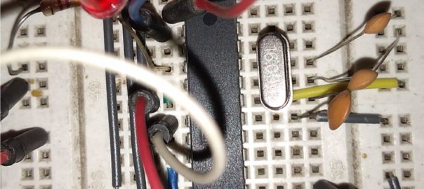
Using Atmega8 or Atmega328p directly without using Arduino boards
Using a 1.44″ Color LCD with Arduino as a display
Recently purchased a cheap color LCD from Ebay (http://www.ebay.com/itm/1-44-Red-Serial-128X128-SPI-Color-TFT-LCD-Module-Display-Replace-Nokia-5110-LCD-/310876068105?hash=item4861a85909:g:9LoAAOSwpzdWqdY~). They are really good for displaying anything (from an Arduino perspective) in color. Though the are cheap and nice, but finding the proper library for them can be a pain. It would be wise to check the details of the LCD and availability of it’s library… Continue reading Using a 1.44″ Color LCD with Arduino as a display
Voltmeter using Arduino
Using precisely calculated resistors and a stable power supply, Arduino can be used to work as a voltmeter. Below is the schematic Though I used an Arduino Uno, but any Arduino can be used. (If the 3.3v versions are used then calculations will have to be done accordingly). The resister for voltage divider has been… Continue reading Voltmeter using Arduino